Earlier posts have shown how to control power by using a relay or by controlling an RF outlet. However, there are use cases that can't be satisfied with those options. Some devices don't have a standard plug you can plug into an outlet. You may want to control the amount of electricity being supplied, perhaps to control the speed of a fan. For those scenarios, you can use a TIP120 transistor.
For our purpose, we will use the transistor to control a higher-voltage circuit. The Raspberry Pi can supply 3.3 volts, which is often not enough to drive the device you are attempting to power. To make things work we will need a few things.
Power supply unit
To supply a higher voltage, we'll use a common power supply unit like this one, which outputs at 12V:
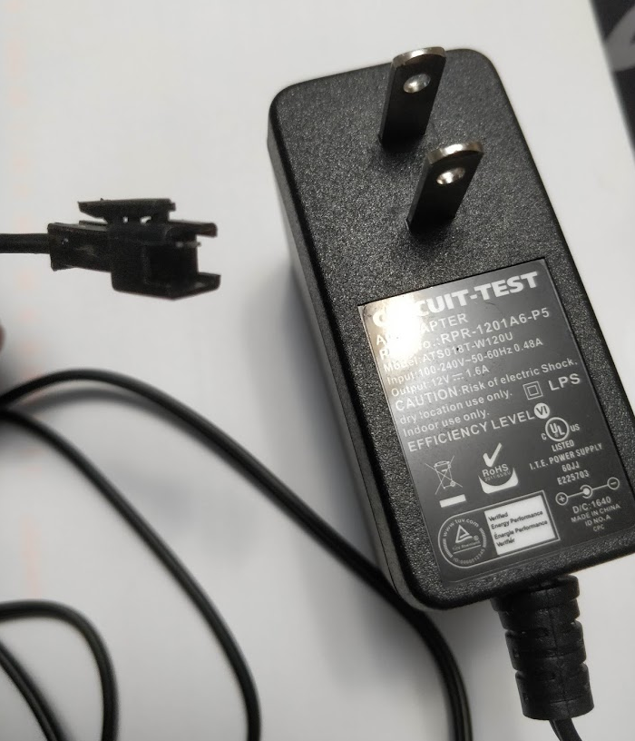
Note that I cut off the normal plug and attached a terminal I got from this set. I won't write about how you use a crimping tool like this one because there are plenty of great Youtube videos that would do better justice to the subject matter, and also because I'm not very good at it :)
TIP120 transistor
This is a cheap and common component you can get from any electronics store.
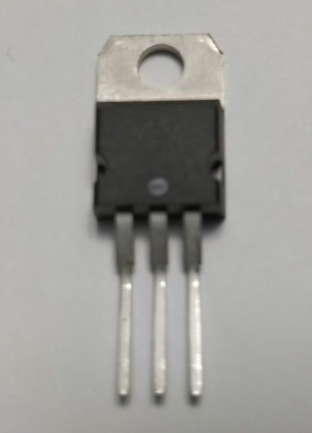
The pins connect to the three parts of the component:
- the base which activates the transistor (left lead in this model)
- the collector which is the positive external lead (center lead in this model)
- the emitter which is the negative external lead (right lead in this model)
To drive a device, we connect the power supply unit and the device into a circuit with this transistor mediating power flow. When we supply current to the base lead from our Raspberry Pi, the transistor will activate and close its circuit which will start supplying the device with power from our power supply unit.
Using pulse width modulation (PWM) via the Raspberry Pi's GPIO18 pin, you can pulse the base lead intermittently, creating duty cycles which supplies and cuts power at desired intervals. This is how you would control the intensity of a fan.
Creating the circuit
To create this circuit you will need:
- 1K ohm resistor
- 1 N4001 diode
- TIP120 transistor
- power supply unit
- a fan or some other device to power
- Raspberry Pi
With those components in hand, the circuit will look like this:
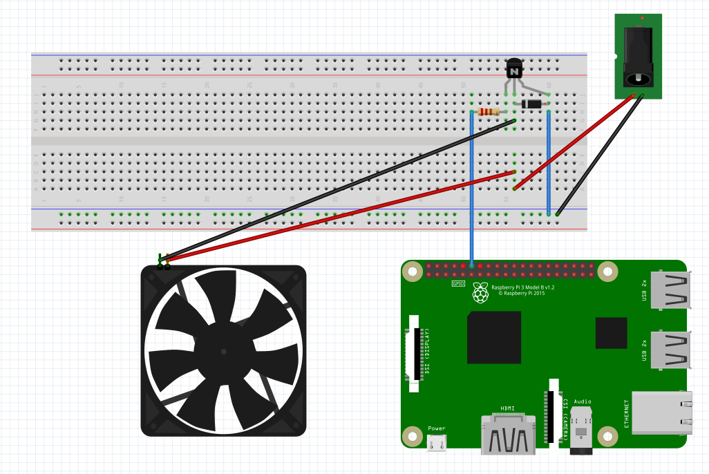
If you wish to use PWM, connect GPIO18 to the base lead of the transistor, which is the leftmost one.
Be sure to include a diode oriented in the direction indicated in the diagram, which ensures current will run in one direction. Without it, a higher current than your Raspberry Pi can handle could run through your board and ruin it.
If you want to turn the current completely on or off, it's just a matter of writing high or not to the pin. To be a bit more interesting, I'll show some code that leverages PWM to control the intensity of a fan. I'll be using Johnny-Five, a great library that let's us create robots and smart devices with Javascript.
import PiIO from 'pi-io';
import five from 'johnny-five';

const board = new five.Board({
  io: new PiIO()
});

board.on("ready", function() {
  board.pinMode('GPIO18', five.Pin.PWM);

  // analogWrite accepts an int between 0-255 which controls the
  // duty cycle supplying power to your device
  board.analogWrite('GPIO18', 1 * 255); // 100% of full power

  // after 5 seconds, reduce to 25%
  setTimeout(() => {
    board.analogWrite('GPIO18', 0.25 * 255); // 25% of full power
  }, 5000);
});
Now that I can control a fan, I am able to control the temperature of my kamodo grill whose temperature is controlled by the amount of air flow through its bottom vent. I can read a bbq probe that is dangling inside my dome, and based on whether the temperature is above or below a threshold I set, the fan will turn on or off to maintain my desired temperature.
You can see below there is a squirrel cage blower that I've connected to my bottom vent via some tubing that is food safe to use at high temperatures.

And yes, that pulled pork was totally delicious.